Fiber Optic Micro-Catheter Pressure Transducers (FISO-LS Series)
Fiber optic blood pressure measurement system for measuring blood pressure in very small vessels, isolated hearts, etc. Pressure measurement occurs at the exact location of interest.
FISO–LS series pressure sensors were designed as semi-disposable for multi-use applications in the life-sciences and small animal research. Unlike its disposable counterpart in clinical applications, this sensor is more robust with a protected tip.
Front Panel:
All evolution Chassis units are composed of the same basic frame elements. Module capacities, communication ports, and overall width specifications differ from one model to the other. The following images show the basic differences between the units.
The power on/off button is located near the top left corner of the front panel. It is a rocking switch. When the top of the button is pushed in, the unit is powered on. To turn the unit off, press in the bottom half of the button. USB communication interface is available on all chassis. This interface allows communication with the computer.
The power source input connector is located under teh I-EVO on all units.
Getting started with your evolution Chassis
Unpacking and Inspection
The evolution Chassis is packaged in a way that provides maximum protection during shipment. If the outside of the shipping carton is damaged, notify your receiving department immediately. Your receiving department may want to notify the carrier.
If the shipping case is not damaged, carefully remove and identify all of the components listed below. Contact FISO or your local representative if any of the components are missing. We recommend you save the shipping case for future storage or transportation.
The SD-2, SD-5 and RM evolution Chassis package should include the following components:
- evolution Chassis unit
- i-evo module
- Power supply adaptor and cord
- USB interface cable
- Module removal tool
- User guide
-
Software can be downloaded at our Support Center!
Inserting and Removing Modules
evolution Chassis are compatible with all evolution modules. During these procedures, be sure to turn-off the power of your chassis and to close the evolution software.
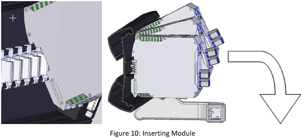
To insert a module in a module slot:
- Tilt the module backwards and hang the top back side on the back plate of the Chassis.
- Align the module with the backplane rail connector.
- Push the bottom of the module back until a clipping sound is heard.
To remove a module from a module slot:
- Insert the provided module removal tool in the module clip slot.
- Tilt the tool upwards to pull the clip downwards and release the module.
- Remove the module by tilting the top backwards and pull it out of the slot.
Connecting the Interfaces
Before proceeding with product setup and use, read the safety information and instructions.
WARNING
To avoid damaging the unit, make sure that the power fed into the power port complies with technical specifications power input range. No other voltage level or range is accepted. The power supply adaptor is provided with the unit. Connect the power supply to the unit power input connector, located under the I-EVO, according to the figure below.
CAUTION
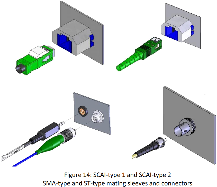
Use care in handling fiber optic connectors. Always clean the fiber end prior to insertion into the connector for optimum performance and to avoid measurement errors. For details on connector handling and maintenance, please refer to section Handling the Sensors.
To Connect the Sensors to the Unit:
- Align the connector key with the slot on the mating sleeve.
- Slide the connector into the sleeve until you hear a clicking sound.
Powering Up the Unit
- Install the software on your computer.
- Make sure that power is off when connecting the power supply to the unit.
- Make sure that all the necessary modules are properly connected to the chassis.
- Connect the USB cable to the computer and your chassis
- Attach the line cord to a power source. Use the power supply provided with the unit.
-
Turn the power on to power up the unit using the ON/OFF switch on the front panel.
Comments
0 comments
Please sign in to leave a comment.